 hotebike
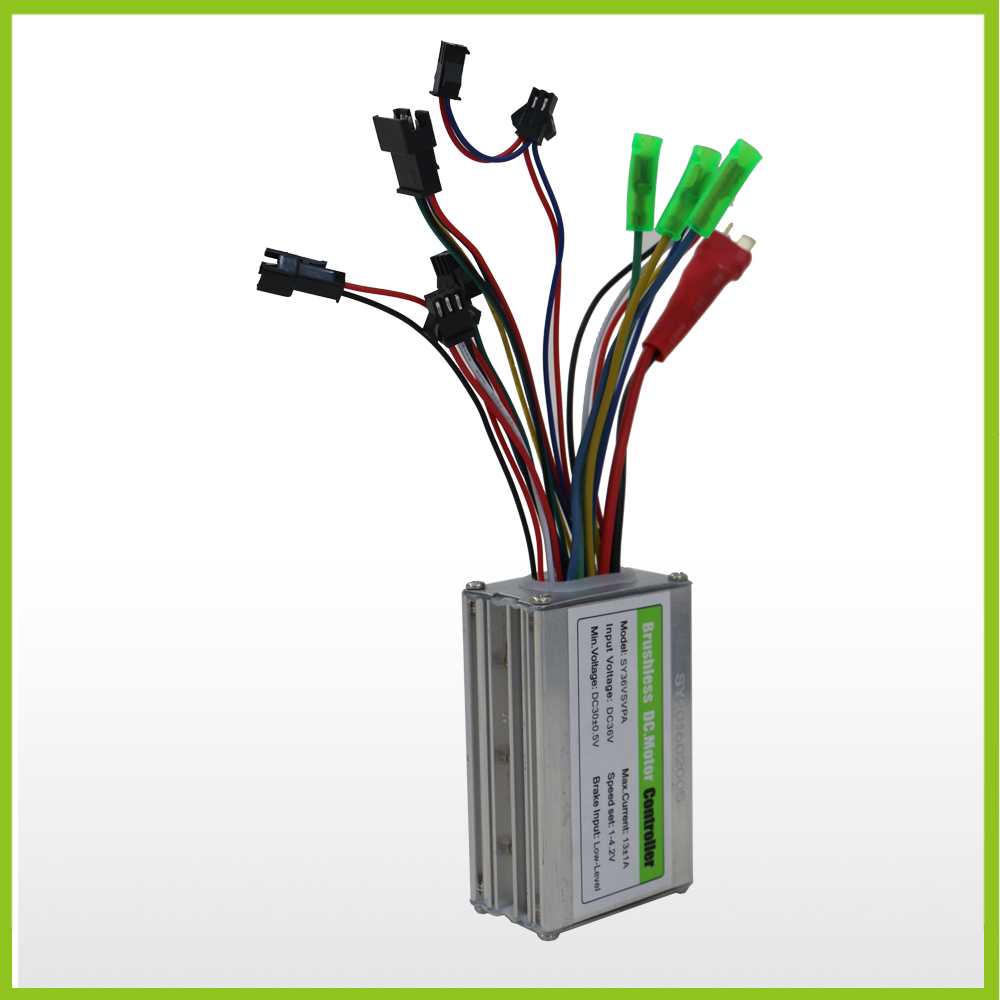
There are a lot of small, but very important parts of electric bicycle and electric bicycle controller is one of them. Although the controller is not very impressive, but your e-bike start, advance and retreat, stop depending on it. So what causes the failure of the e-bike controller?
1.Power device damage
Power device damage, generally there are the following possible: motor damage caused by; The power of the poor quality of the device itself or the selection of grades caused by insufficient; Device installation or vibration caused by loose; Motor overload caused; Power device drive circuit damage or unreasonable parameter design caused.
2.Internal power supply of the controller is damaged
The controller internal power supply damage, generally has the following several possible: the controller internal circuit short circuit; Short circuit of peripheral control unit; The external lead shorted out.
3.The controller works intermittently
The controller works intermittently, generally there are the following possibilities: the device itself in the high temperature or low temperature environment parameter drift; The high power consumption in the overall design of the controller leads to the high local temperature of some devices and the device itself enters the protection state. Poor contact.
4.Loss of control signal caused by wear of connection wire and defective or falling off connector
Connector wear and contact plug-in bad contact or fall off, there are generally the following possible: unreasonable choice of wire; Incomplete protection of wire; The connector is not tightly pressed.
Controller identification
1.Observe the workmanship carefully
The work of a controller reflects the strength of a company. Under the same conditions, the workshop controller is certainly not as good as the product of a large company. Manual welding products are not as good as wave welding products; A fine-looking controller is better than a product that doesn’t care about appearance; A controller that USES thick wires is better than one that cuts corners on wires. The controller with heavy radiator is better than the controller with light radiator to wait a moment, the company that pursues somewhat with makings and craft is opposite credibility tall, contrast can see.
2.Compare the temperature rise
From with the new controller and original use forward controller in the same condition of the hot test, two controllers are torn down, radiator in a car, hold up, turn the turn first to reach the top speed, brake immediately, don’t brake to death, so that the controller into the wall protection, at very low speed lasts for 5 seconds, loosen the brake and quickly achieve the high speed, brake again, again and again the same operation, such as 30 times, the highest temperature point detection of radiator.
Compare the two controllers. The lower the temperature, the better. Test conditions should ensure the same current limit, the same battery capacity, the same car, the same starting from the cold car test, maintain the same brake force and time. At the end of the test, the tightness of the screw fixing MOS should be checked. The looser it is, the worse the temperature tolerance of insulating plastic particles used will be. In long-term use, MOS will be damaged due to heat in advance. Then install the radiator and repeat the above test to compare the radiator temperature, which can investigate the cooling design of the controller.
3.Observe the back pressure control ability
Select a car, the power can be a little larger, pull out the battery, choose the charger for electric vehicle power supply, connected to the e-abs enable terminal, ensure that the brake handle switch contact well. Slowly turn the handle, too fast charger can not output a large amount of current, will cause undervoltage, let the motor reach the highest speed, fast brake, repeatedly, should not appear MOS damage phenomenon.
When braking, the voltage at the output end of the charger will rise rapidly, testing the instantaneous voltage limiting ability of the controller. This test will have no effect if it is tested by battery. The test can also be carried out on a fast descent, with the brakes applied when the car reaches maximum speed.
4.Current control ability
Connect the full battery, the larger the capacity, the better, first let the motor reach the maximum speed, choose two motor output line short circuit, repeated, more than 30 times, should not appear MOS damage; Then let the motor reach the highest speed, use the battery anode and an optional motor wire short circuit, repeated 30 times, this is more severe than the above test, the circuit is less a MOS internal resistance, instantaneous short circuit current is larger, test the controller’s current rapid control ability.
Many controllers will make a fool of themselves in this link. If damage occurs, we can compare the number of times that two controllers successfully bear short circuit. Pull out one motor line and turn it to the maximum value. At this time, the motor will not run. Switch on another motor line quickly and the motor should be able to rotate immediately. This part of the experiment can verify the reliability design of the controller software and hardware.
5.Check the efficiency of controller
Turn off the overspeed feature. If there is one, test the maximum speed achieved by different controllers in the same vehicle with no load. The higher the maximum speed, the higher the efficiency and the higher the range.
One: when the electric vehicle has a brush controller but no output
1.Set the multimeter at +20 transmission (DC) gear, and first measure the high and low potential of the output signal of the gate.
2. If pinch the brake handle, the brake handle signal has more than 4V potential change, can eliminate the brake handle fault.
3.Then conduct circuit analysis according to the commonly used upper foot function table of the brush controller and the voltage value of the main control logic chip measured, and check whether the values of the peripheral components of each chip (resistor, capacitor, diode) are consistent with the identification on the surface of the components.
4.finally check the peripheral devices or integrated circuit fault, we can replace the same type of devices to solve the problem.
 Two: when the electric vehicle brushless controller completely no output
1.Check the measurement diagram of brushless motor controller’s main phase, and use the multimeter dc voltage +50V to test whether the 6-way MOS tube gate voltage corresponds to the rotation Angle of the rotor.
2.If there is no right, it means that there is a fault in the PWM circuit or the MOS driver circuit in the controller.
3.By referring to the main phase diagram of brushless controller, measure whether the voltage of the input and output pins of the chip has a corresponding relationship with the rotation Angle of the switch, and judge which chips have faults. The fault can be solved by replacing the same type of chip.
Three: when the electric vehicle brush controller control parts of the power supply is not normal
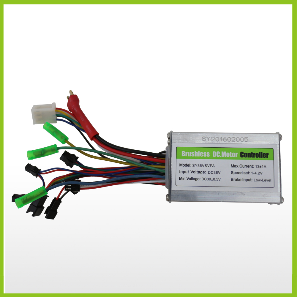
1.The internal power supply of electric vehicle controller generally adopts three-terminal voltage stabilizing integrated circuit, and generally USES 7805, 7806, 7812 and 7815 three-terminal voltage stabilizing integrated circuit, whose output voltage is 5V, 6V, 12V and 15V respectively.
2.the multimeter set in DC voltage +20V(DC) gear, the multimeter black pen and red pen respectively rely on the handle of the black line and red line, observe whether the multimeter reading is consistent with the nominal voltage, their voltage difference should not exceed 0.2V.
3.Otherwise, it indicates that the internal power supply of the controller fails. Generally, a brush controller can be used to eliminate the fault by replacing the three-terminal voltage regulator integrated circuit.
Four: when the electric vehicle brushless controller lack of phase
Electric vehicle brushless controller power supply and brake handle fault can be referred to the brush controller troubleshooting method to first eliminate, for the brushless controller, there are its own fault phenomenon, such as phase missing. Brushless controller phase deficiency of electric vehicle can be divided into main phase deficiency and hall phase deficiency.
1.The detection method of main phase missing phase can refer to the brush controller troubleshooting method of electric vehicle to detect whether the MOS tube breaks down. The breakdown of the MOS tube of the brushless controller is generally that the upper and lower two pairs of MOS tubes of a certain phase break down at the same time. Check measuring points.
2.The hall phase deficiency of brushless controller of electric vehicle is manifested as that the controller cannot recognize the motor hall signal.
How to fix a 36v electric bike controller
Prev: 26” electric mountain bike A6AH26 instrcution manual
Next: Mountain Bike Getting Started Guide 丨 27.5 VS 29 Which wheel diameter is more suitable for you