 hotebike
How to make an electric bike with a starter motor

In the electric bicycle industry, the motor generally refers to the motor assembly, including the motor center, reducer, etc. The electric bicycle that we say below all is electric motor assembly.
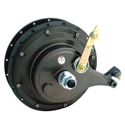
(1) Motor disassembly
Before removing the motor, the lead wires of the motor and the controller should be unplugged first. At this time, the one-to-one correspondence between the lead color of the motor and the lead color of the controller must be recorded. Clean the operating area before opening the motor end cover to prevent sundries from being absorbed on the magnetic steel inside the motor. Mark the relative position of end cap and hub. Note: be sure to loosen the screws in diagonal order to avoid deformation of the motor housing. The radial gap between the rotor and stator of the motor is called air gap, and the air gap of general motor is between 0.25-0.8mm. After removing the motor to eliminate the motor fault, be sure to follow the original end cover mark for assembly, so as to prevent the cleaning phenomenon after the second assembly.
(2) Lubrication of the gear in the motor
If there is a brush with a gear hub motor and brushless with a gear hub motor running noise starts to increase, or replace the gear in the motor, should be all gear tooth surface coated with grease, generally use no. 3 grease or manufacturer designated lubricating oil.
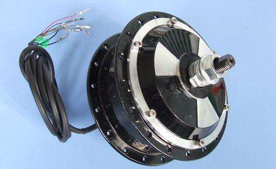
(3) Motor assembly
Before assembling the brush motor, please check the elasticity of the spring inside the brush holder, check whether the carbon brush and the brush holder are rubbed, check whether the carbon brush can achieve the maximum stroke in the brush holder, and pay attention to the correct positioning of the carbon brush and the phase changer, so as to avoid bad carbon brush or brush grip.
When installing the motor, the impurities on the surface of the motor parts should be cleaned first, so as not to affect the normal operation of the motor, and the wheel hub body must be firmly fixed, so as not to cause collision and damage of the components due to the strong attraction of magnetic steel during installation. Test 36V normal, controller output 5V, 12V normal, normal motor resistance. Connect the motor directly to the 36V battery, and the motor works normally.
(4)Wiring method
Due to different commutations, brushless and brushless motors not only have different internal structures, but also have great difference in connection mode.
1.Wiring method of brush motor. Brush motors generally have plus or minus two leads. Generally, the red line is the positive pole of the motor, and the black line is the negative pole of the motor. If the positive and negative pole switch wiring, will only make the motor reverse, generally will not damage the motor.
2.Brushless motor phase Angle judgment. The phase Angle of the brushless motor is the abbreviation of the phase algebraic Angle of the brushless motor. The common phase algebraic angles of brushless motor used in electric vehicles are 120° and 60°.
Observe the installation space position of hall element to judge the phase Angle of brushless motor. The installation space position of hall element of 120° and 60° phase Angle motor is different.
Measure hall true signal to judge the phase Angle of brushless motor
What needs to be explained first is what is called the brushless motor magnetic tension Angle. Brushless motors generally have 12, 16 or 18 pieces of magnetic steel, and corresponding stator slots are 36, 48 or 54 slots. When the motor is at rest, the magnetic force line of the rotor magnet steel has the characteristic of walking along the direction of minimum reluctance, so the position where the rotor magnet steel stops is exactly the position of the convex pole of the stator slot. The magnetic steel does not stop at the stator core, so there are only 36, 48 or 54 positions between the rotor and the stator. Therefore, the minimum magnetic tension Angle of brushless motor is 360/36°, 360/48° or 360/54°.
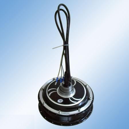
The hall element of brushless motor has 5 leads, which are the positive pole of the common power source, the negative pole of the common power source, the A phase hall output, the B phase hall output and the C phase hall output. We can use the five hall leads of the brushless controller (60° or 120°) to connect the positive and negative power of the hall leads of the brushless motor, and connect the leads of the other three phase sensors A, B and C to the hall signal leads of the controller at will. The phase Angle of brushless motor can be detected by switching on the power of the controller and feeding the power to the hall element.
The method is as follows: use the +20V dc voltage block of the multimeter, and measure the voltage of the three leads with the black meter pen grounding wire and the red meter pen respectively, and record the high and low voltage of the three leads. Rotate the motor slightly and make it rotate by a minimum magnetic tension Angle. Measure and record the high and low voltages of 3 leads again, and do so for 6 times. We use 1 to represent the high potential and 0 to represent the low potential. So — if the brushless motor is 60° and continuously rotates 6 minimum magnetic tension angles, the hall truth signal measured should be 100, 110, 111, 011, 001, 000. Adjust the pin order of the leads of the three hall elements, and make the truth signal change strictly in accordance with the above truth order, so as to judge the phase A, B and C of the brushless motor with 60°.
If the brushless motor is 120° and continuously rotates 6 minimum magnetic tension angles, the hall truth signal measured should change according to the rule of 100, 110, 010, 011, 001, 101, so that the current phase sequence of hall element leads can be determined.
If you want to quickly determine whether the brushless motor is 60° or 120°, use the +20V dc voltage block of the multimeter, and measure the voltage of the three leads respectively with the black meter pen grounding wire and the red meter pen. When the three wires have voltage or no voltage, determine the motor is 60°, otherwise it is 120°
3.Wiring method of brushless motor. Brushless motor has 3 coil leads and 5 hall leads. These 8 leads must correspond to the corresponding leads of the controller, otherwise the motor cannot rotate normally.
Generally speaking, brushless motor with phase Angle of 60° and 120° needs to be driven by brushless motor controller with corresponding phase Angle of 60° and 120°. The controller with two phase angles cannot be directly interchanged. The brushless motor with 60° phase Angle and the 8 wires connected to the 60° phase Angle controller can be correctly connected in two ways: one is forward rotation, the other is reverse rotation.
For brushless motor with phase Angle of 120°, by adjusting phase sequence of coil lead and phase sequence of hall lead, 6 kinds of correct connections can be made for 8 wires connected by the motor and the controller, among which 3 are connected by forward rotation of the motor, and the other 3 are connected by backward rotation of the motor.
If the brushless motor reverses, indicating that the phase Angle of the brushless controller and the brushless motor matches, we can adjust the direction of the motor in this way: switch the A and C of the brushless motor and the hall lead of the brushless controller; Meanwhile, the main phase lines A and B of the brushless motor and the brushless controller are exchanged.
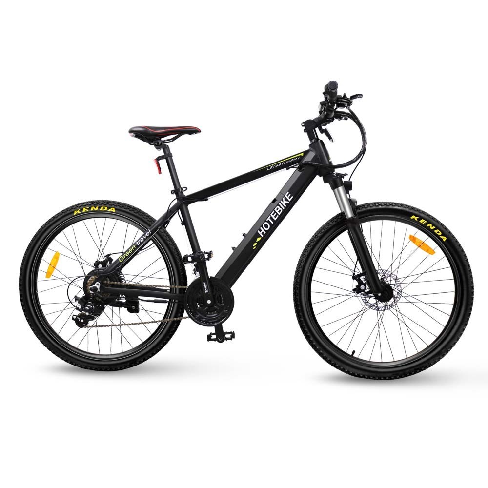
Electric bikes come in three general types. 1. Dc hub motor, namely brush motor, two outgoing lines, external PWM controller. 2. Ac hub motor with or without hall sensor, more than three leads, external frequency conversion controller. 3. Brushless dc wheel hub motor, including electronic commutator and two outgoing wires. External PWM controller. Be sure not to be confused.
BEST MODEL BIG SALE ON AMAZON,JUST SEARCH “HOTEBIKE”